
Manufacturing
of Fuel Cells
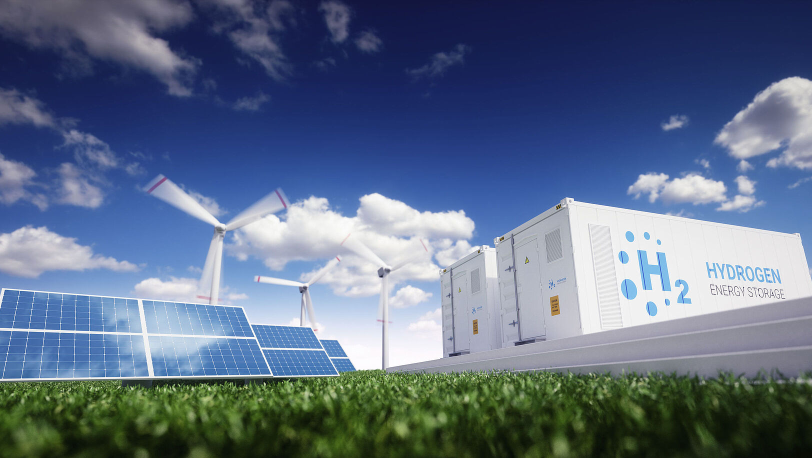
In hydrogen‑powered vehicles or as decentralized energy suppliers, fuel cells energize modern life: they impress with high efficiency and pave the way toward a sustainable technology landscape. As electrolyzers, they also enable the production of green hydrogen.
Their manufacture requires comprehensive process know‑how. This is exactly where our strength lies: integrating individual production steps into a seamless, high‑performance overall concept – from membrane processing to the finished stack.
Efficient material logistics ensure stable operations, precise printing processes enable the handling of sensitive substrates, and laser technologies support key steps such as welding or cutting. For the assembly of complex modules, we work with INVENTUS to implement tailored automation solutions, including integrated quality control.
This results in a holistic approach to fuel cell production – from individual machines to turnkey production lines.
Contact Person
Do you have any questions?
Find your local contact with our Contact Finder.
Contact Finder
Follow us on LinkedIn
Find out everything about our products and events in the field of Energy.
Fuel Cells
A fuel cell usually consists of a membrane electrode assembly (MEA), which is enclosed by two metallic pole plates (bipolar plates). The anode and cathode gases hydrogen and oxygen are transported through the pole plates to the MEA. The actual electrochemical reaction to generate electricity takes place in here. A broad differentiation of fuel cells is based on the operating temperature. While „low temperature“ fuel cells usually operate in the range of <100°C, the operating temperature of a „high temperature“ fuel cell is in the range of 700°-1000°C. High-temperature cells are currently based on ceramic membrane materials (SOFC) or metallic membrane materials (MSC).
ASYS Group Process Steps
Bipolar Plate
Polymer Electrolyte Membrane Fuel Cell (PEMFC)
Low-Temperature Fuel Cell
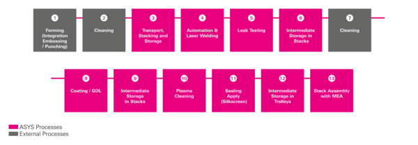
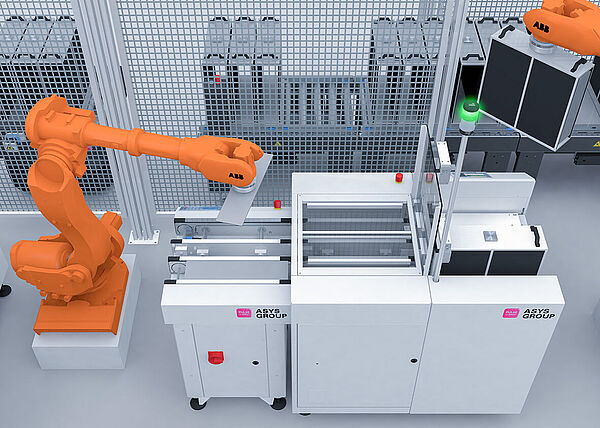
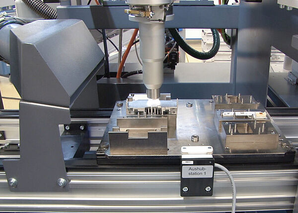
The laser welding system integrated into the line concept is loaded with stacks of stamped sheets for the anode and cathode sides. They are automatically aligned with each other using an optical system, stacked, fixed in place, and welded. Optionally, the result can be checked inline for leak tightness. Any potentially defective bipolar plates are sorted out immediately, and only good parts are temporarily stored in a stack.
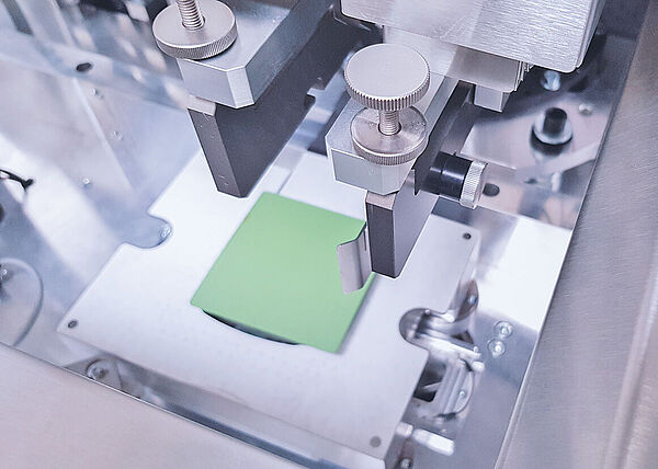
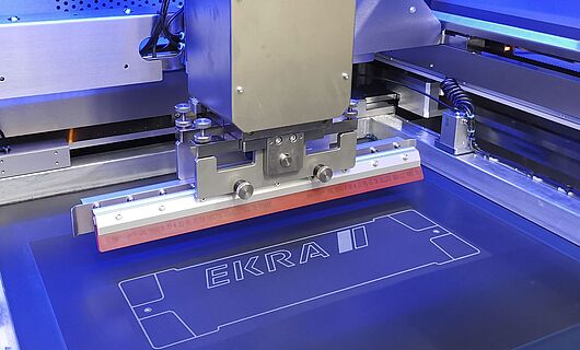
A wide variety of elastomers or silicones suitable for use as sealing materials can be applied using the screen printing process. Depending on the material, uniform layer thicknesses with a tolerance of ±5 µm can be achieved. Cycle time plays a decisive role in cost efficiency at this process step; therefore, two bipolar plates are processed in parallel in the printing line. Within 3 seconds, they are placed on the printing table using grippers, mechanically aligned, and printed. While the printed plates are conveyed out via conveyor belts, the next parts can already be placed. After passing through the drying oven, they are turned and temporarily stored as a stack or fed directly into a second printer for backside printing.
To improve the electrical contact with the MEA, bipolar plates are coated. This involves contact prints (bipolar plate to MEA) using a special coating method followed by subsequent inspection.
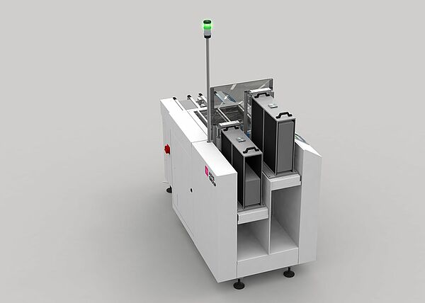
Transport of the materials from the production station to an automated intermediate storage facility. This can be carried out manually or fully automatically. Intermediate storage can take place in an ASYS Material Warehouse. Communication is handled via a manufacturing execution/control system.
To achieve the desired performance of the fuel cell units, MEAs are stacked with bipolar plates on both sides. At the same time, the stack is connected to the end plates and either bolted or clamped together. For automation, solutions tailored to the required cycle time are developed and implemented.
ASYS Group Process Steps
Membrane Electrode Assembly
High Temperature Fuel Cells
Solid-Oxid Fuel Cells (SOFC)
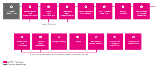
Depending on the technology, we offer solutions for printing the layers onto either the unsintered or already sintered membrane. Printing can be carried out both in a single-sheet process and directly from the roll (RtR).
Trimming of the sintered membrane is performed using a laser. In this step, the membrane can also be given a unique identification (e.g., a DMC code).
The fired and cut ceramic half-cells can be further printed with multiple layers. Established machine concepts from the solar industry can be used for this purpose. This ensures material‑gentle transport (substrate handling) with very short cycle times and uniform layer thicknesses.
To achieve the desired performance of the fuel cell units, MEAs are stacked with bipolar plates on both sides. At the same time, the stack is connected to the end plates and either bolted or clamped together. For automation, solutions tailored to the required cycle time are developed and implemented.
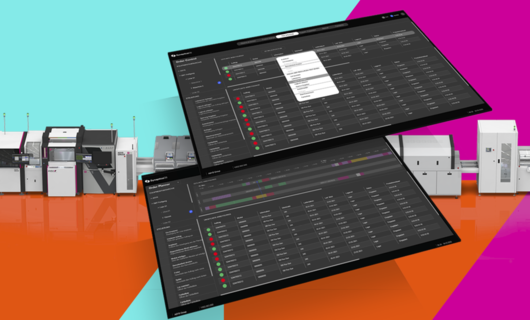
For product traceability and machine communication, we offer various interfaces and software solutions. All ASYS production concepts can therefore be individually connected to different database systems. In addition, the comprehensive software platform **SynapticaOS** supports operators in production.
Sintering of the membrane at temperatures of around 900 °C is carried out in stand-alone or inline systems. These are integrated into the automation solution. Depending on the concept, the sintered substrates are temporarily stored in magazines for further processing in the cutting laser.
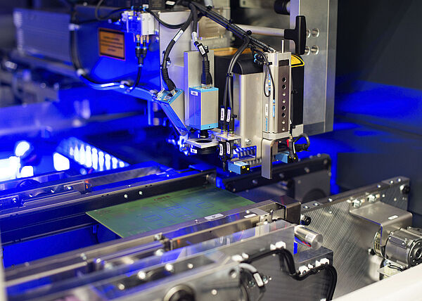
Print quality control in fully automated lines is carried out either via weight control or through integrated inspection systems (3D inspection).
The substrates or bipolar plates are transported from the production station to an automated intermediate storage system. This can be carried out manually or fully automatically. Intermediate storage can take place in an ASYS Material Warehouse. Communication is handled via a manufacturing control system.
Due to the high operating temperatures in solid oxide fuel cells, the sealing materials must be highly temperature‑resistant. Therefore, pastes based on glass, glass ceramics, or metals are often used for seal printing. These pastes are highly abrasive and require careful adjustment of the printing processes to avoid excessive material wear.